Monday, August 4, 2014

Hot stuff

As a change from beating an infuriating piece of stainless steel one of the other pre-body fit tasks is to sort the heater.

This is a donor item from a polo Mk2/3 which AK kindly sourced for me as I wasn't having much luck.

It's a pain to get to and virtually impossible to fit if the body is on chassis with engine in.

So. First check it's a runner with a bit of testing with the ammeter and then checking the wires with a bit of 12volts. Good fun and it's definitely a runner with 3 speeds.
The IVA test requires a windscreen delisting device which doesn't require the use of a human hand smearing a small window. Hence the need for the fan. Plus passengers do like a bit of hot air on their feet in winter.


Labelled up I can now take it to pieces to do a thorough clean.

Expected issues that need addressing - matrix degradation due to age. £24 no postage from eBay in Germany sees a new one delivered in 3 days inc foam.

And the valve featured above has an oring which leaks as soon as other builders have connected up their pride and joys...


So that's coming out and a replacement sourced for a few pennies from B and Q is installed with a bit of red rubber grease.

One of the other key IVA criteria is not to have any engine compartment air feeing into the heater fan. So this needs blocking off (B&Q have a nice guttering down pipe adapter thing which with the offset outlet means once you trim off the outside ring it's perfect for fitting between the hot water pipes.

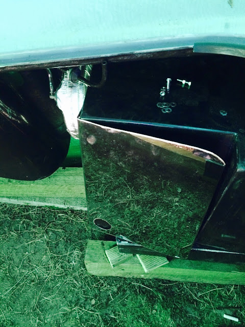
This then needs one more flange from car builder solutons to connect to the bulkhead to draw air in from the passenger footwell.

Which should be the angled black GRP on LHS of the above photo next to the stainless engine bay cladding that I've just fitted!

The motor end of the heater is also open. The opinions are split as to whether it actually draws much air across it or not. I was originally going to leave open but again for IVA belt and braces I've now made a closed end cover for this too using part of a sanitary ware fitting from homebase and a shaped with a Stanley knife.

Above ready to cover
A healthy dose of sealant applied
And the main input end cover sealed on. I'm going to be using a 68mm flexible wire reinforced hose from CBS to allow a good airflow, which will mate to this flange below on the bulkhead (also from CBS)


Cutting the aperture for the heater was fun. Really, it was. I had forgotten how grim fibreglass dust is until I started cutting with the dremel. In hindsight a more coarse cut and less speed approach will be used for the boot floor cutout for fuel filler etc. Having made myself look like a ghost with a bit if fettling of the heater box itself I got it located in what I'm hoping is the right place.

And from the inside...


Just the motor cover to fit with inlet hose too and then I can seal this all in.

Function over form

Originally I was hoping to hide the transmission cooler between the radiator and the cooling fan and whilst I could do that it's a bit of a squeeze and not really allowing the transmission cooler to do the best job it could. 

An unknown is also if it's temperature went too high would it also trigger the fan to run through the communication line between the TCM and the ECM. I'd rather not test this in traffic given how sensitive these transmissions are about overheating.

So the other options are to use a laminova style water cooler (might still need one anyway) or locate the cooler in front of the radiator.


Well a couple of brackets later... And some Aluminium paint for the front of the cooler


And we have a front mounting cooler with the correct air gap between it and the radiator blended in as much as possible. With the wind splitter in the nose this hopefully won't look too ugly... And if it does, well at least my transmission will be cool. Ish.


Just a bit of hose securing to be done and that's another job done.

Thursday, July 31, 2014

Ticked off.

Not as in angry man. Some jobs are done! 

Design and fit new diff cover for fuel hoses. Designed and still doesn't fit. It's painful, I have been making it harder by not removing silencer boxes first but I felt I needed the full exhaust in place to help with location.
I bet BMW and Mercedes don't use Rice Crispies boxes to help with pattern making for suppliers!


It's had a few trial fits - I'm getting closer. I do a bit and then put it down for a few days until I feel inspired enough again to have another go.

Send electronic accelerator pedal to AK to make up pedal box
This was sent with Mr Kellogs cardboard pattern above to AK who turned it around lightening fast along with making diff cover v3 and so I had it back with pedal box.

Above you can see the pedal box along with the Corvette 'gas ' pedal in situ. Managed to use the brake booster studs to locate accelerator pedal too with a little bit of fettling of the accelerator pedal bracket to allow nut to seat properly. Works a treat. 
Was a bit more challenging to get it fitted into the car body. Much sweat, bruised ribs from lying on side on transmission tunnel and general shouting (I hate you might have been aired once or twice) trying to get them fitted whilst opening up holes with drill extension above my head, upside down on one of the hottest days of the year in the drivers footwell. 

It's in. I forgot to take a photo of the accelerator pedal being in too. The pain was too much and I had to walk away!


The brake booster has been heat protected with special tape - although given that it's a vacuum in there and it's a vacuum being refreshed by the engine intake all the time it seems a bit overkit but someone else did it and I thought it was a good idea too


Just got to pop nylocks on and then fit the cladding, open up the cable hole at bottom and that bit is done. One of the less enjoyable tasks!

Replace rubber washer in polo heater valve - done and I will cover in a separate post as it's an important one for IVA rule conformity.

Gear lever position has been approximated and gear lever with correct detents (indents to you or I- the bits that lock he lever into position) for my transmission has been ordered from the States.
Whilst I could have had a go doing this myself it's a really important part that if I muff it up will leave us stranded somewhere or just look homemade in a highly visible focal point of the car. 

Fit engine bay cladding
Started and have since chatted to AK to find out best order for doing this so need to find some weekend time to do the rest.

Fit heater matrix into body
Have had a test measure and another chat with Job about locating this as I really don't want to make a mistake with this. Will have a go when I get back outside for a good stint.

Sunday, July 13, 2014

Next in the task list

The list of things that need doing before I can get the body ready to go on are these:

Design and fit new diff cover for fuel hoses
Relocate the coil packs (see below)
Modify engine loom and re cover
Send electronic accelerator pedal to AK to make up pedal box
Replace rubber washer in polo heater valve
Measure and triangulate locations for the body cut outs for fuel filler and sender in the boot.
Same for gear lever position
Fit engine bay cladding
Fit heater matrix into body

So for the coil packs - they are not that attractive on top of the valve covers but more importantly I've already melted one of the spark lead boots where it touched the headers.

The IVA test won't like this so I need to move the coil packs and make up some different leads with a better routing away from the headers.

So lots to do in the coming months!

Bits and bobs

Lots of little post start up jobs to complete before I can seriously look at getting the body on.

Exhaust needs sealing up - the headers to main tubes first
Using Holts Firegum exhaust sealant that goes semi hard when heated up. Smear a good section over the male pipe being careful not to check any down the tube or on top edge as I don't think the cats will like it.
With the exhaust clamps tightened up a little bit squeezes through the petals showing what I think is the right amount to get a good seal.
Both sides are done. 
I'm not doing the other join yet until I've finished fiddling around with the fuel line cover under the differential at the rear. The standard AK one isn't fitting well - not an issue with the part more that my unique configuration is causing non standard fitment issues. So I've mocked up in cardboard the new shape / profile and will send the old one back to AK with the mock up to get a custom one made. Whilst it's not an IVA must have, the fuel line does pass less than an inch away from the exhaust line at the junction with the swirl pot so I would rather have some shielding in there.
See photo of old one.

Other tasks done.
Air intake. I've cleaned up the slot in the intake tube and made the bolt holes and threads for the Mass Airflow Sensor (MAF). 


I've modified the bung to take countersunk bolts as opposed to the normal method of welding on.
I've made a temporary rubber grommet which I might actually remake as a permanent part - originally I was going to use araldite metal bond to permanently fix the bung onto the stainless but now I'm thinking a rubber grommet or gasket will be more forgiving on the fitting.
MAF in situ. 

Next up the final hose clamp for fuel lines. Now I have resolved leaks, know that adequate fuel is getting to the engine  even with only a couple of litres in the tank there's enough gravity feed I can make the fuel lines a permanent fix. Look at where they run over the chassis rail and under the differential I've managed to reuse a hole that also anchors the nearside rear brake line. 

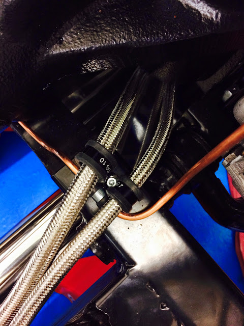
A longer bolt and good planning means the brake line is attached followed by fuel feed and return line and importantly the fuel lines cannot chafe on the chassis rail, nor on the brake line and all is secure. Hopefully leading to a happy IVA tester.


It is going to be interesting getting to this bolt if I ever have to change the lines once the body is on!


It's still alive...

Clearly rendered speechless by the fact the engine actually started, the last post was a bit lacking in content.
So, review time. The engine starts, it runs. There's one code in the computer at the moment which indicates too higher voltage from the oil pressure sensor. There is oil pressure so I'm not too worried at the moment - I've got a mechanical oil pressure sensor to double check - just waiting for an adapter to arrive. Then probably a case of getting a new sensor. That it in the below photo with the blue grey locking clip.


Whilst we are on that photo I also rigged up the brake vacuum booster... Above shows the vacuum connector from the intake plenum, I've shortened the feed hose as now the engine is in a right hand drive car the line needs to double back on itself. From there it passes through a sensor and then to the brake booster hose. I've borrowed a bit of the old transmission cooler line to jury rig. 

I'm pleased to say success! The temporary 'pedal lever' I set up takes a full handed push to brake the front wheels. With engine running it just takes two fingers. Nice and light. Very happy with that!


Other things tested - my oversized fan was wired up, warmed the engine up and at 94 degrees c the fan kicked in on the normal / slow speed setting for about 45 seconds till the temp dropped to 92. I'd say that was a success but need to check what the programmed fan on low and high speed actually are and what sort of temperature I should be aiming for.
The one challenge is that the transmission cooler is temporarily suspended behind the fan - it really needs moving in front of the actual radiator so some brackets need fabricating for that. I'm also goin to spray it an aluminium colour to blend into the radiator.
Finally transmission fluid was set. This a convoluted and painful process. There's no dipstick for it. The car has to be level, the transmission warmed up to between 30 and 50 degrees. Any higher or lower will result in the wrong level as the fluid expands or contracts based on temp and therefore potentially shorten the life of the transmission. The final part of this is having to run the trans through all the gear selection positions.
So duly levelled and warmed on axle stands I then had to slither underneath whilst the engine is running to open the fluid level drain plug. Let fluid run out till it drips - if no fluid drips out then fill some more till it does. On third attempt it was right so the plug goes back in and torqued up to the right spec. This should not need looking at for 50k miles now. 
Another job ticked off the list.

Whilst we had it running I wanted to check whether the tap shift electronic gear change was working. I put into sprit mode but not sure if it's actually working. As the drive shaft isn't in and clearly not pushing the wheels against the road I think the transmission is not getting the right feedback (newtons 2nd? law of an action having an equal and opposite reaction) and that's not being passed through to the engine either so it could be that. Will have to wait until we are on the road to test.

In normal drive mode the gears definitely changed and the speed registered car speed from calculated values so that is all good!

One small fuel leak to resolve - I had only done the feed from tank to first filter up by hand so once done up properly is fine.

Also, the lower return hose from radiator had a small drip too so I've nipped he clamp up a bit more. I will get another on there to double up and enable me to tweak the positions a bit.

Sunday, June 29, 2014

It is alive!

As many have proclaimed before, it's alive.

I got to this point much sooner than I originally thought possible...


Monday, June 23, 2014

Crimpage


Got a new toy recently - a hydraulic crimper. All the instructions are in Chinese so possible it might not last long as it wasn't expensive however it's very very satisfying to use.

I'm crimping my own battery cables (50mm squared for the starter/positive run from battery at rear and negative to chassis) which means standard spade terminal crumpets aren't big enough.
Enter the big one - can't remember how much force it can exert but it's in the tonnes. Crimps anything from 2.5mm squared to 70mm squared.

The result is beautiful hexagonal crimps.

And if made my first battery cable.


Fuel sender and gasket

Take one of these

Fuel sender. Measures something like 33 ohms empty and 240ohms full. 
Measure depth of tank and then draw out profile on a piece of paper. Then I used some masking tape on the wire to show approximate level of where the float needed to be. It's secured to the wire by just circling around a narrow bar to make a spring loop which then slots into the recess on the float.
Deliberately I left the float position so that it would be more accurate measuring the low point than the high - whilst the tank will register full for a bit after filling I don't mind the optimistic feeling that will give me that I'm driving economically. Ho ho.

Further more, the arm is angled to deliberately sit about an inch off the bottom of the tank. This means with a bit of maths I should be able to work out exactly the remaining volume when the needle is on "E" and therefore how many miles I have left if petrol stations are hard to come by. Nifty eh?
So above is the inch safety margin on empty.


Then using some of this stuff - special gasket paper a set of compasses and a leather hole punch device kindly lent by a neighbour 


And we have a gasket made. I won't bolt it in to the tank yet but just a case of some blue hylomar gasket seal on either side and around the holes and we have a sealed sender.

Amazingly all the holes line up!

Sunday, June 22, 2014

Waterworks

Having successfully created a cosmic (according to some) cooling system route to navigate around the steering column clearance needed I have made the following decisions:

1. Remove anti-roll bar on he front suspension. Will refit at a later date once I've finished getting the cooling sorted. The cooling is more important.

2. Bite the bullet on the transmission cooler. It needs to go in front of the radiator although I don't like the idea of what it will look like. I have some aluminium paint to help it blend into the radiator.

3. Stick with the 17" fan. Whilst there's a bit if a gap round the edge of it I can always make a shroud in the future if overheating is an issue, it shifts a lot of air. All the dust that was under the car is now at the back of the garage courtesy of the first trial run - and that wasn't on the high speed!

So. The below shows where I am up to. The two things left here are the open pipe on the air intake for the crankcase ventilation tube and and the mass airflow sensor which needs to go into the air intake.


Friday, June 20, 2014

Big update


Where to start? I've been acquiring parts left right and centre; fuel tank, header tank, shiny air intake, engine bay cladding (shiny), hoses, radiator, cooling fan (large) and wheels. Yes, wheels, not so shiny to start with but they are improved alread. Some chap had to sell his part built kit with additional spare wheels so I helpfully took his 16" rims with black centres off his hands.

16s were always my plan as surrey council don't seem to think pothole repair  is their responsibility so a rough ride should be tempered by these.

I'm very taken with the look though. Oh, and they came with my choice of tyres too.


Fuel line connecting to tank taking place here - Jon welded the AN bungs onto the inbuilt swirl pot for me. Just the cover plate to go over the hoses under the diff for additional protection from bumps.


Happy with exhaust position now so have fully tightened the brackets. I won't seal the joints until I've test ran engine in case I have to pop it out for any reason.


 Above view from tank. Held in place with 5 M8 bolts that are in threaded holes directly on the chassis. I will probably loctite these once I'm happy with everything so I don't lose tank when out and about.

 
Bit of tweaking required for water header tank position. I will use a couple of pieces of 1/8 aluminium flat to raise it up under the brackets to help along to radiator position.


The water thermostat position is a bit of a challenge with the L99 engine as it's further out in front of the engine meaning the hose can't take the usual LS3 route without fouling the serpentine belt or steering column shaft. However a bit of work with a protractor and a 180 degree bend trimmed from Viper Performance and the convoluted result can be seen. 


The white tie is supporting the stainless lower tube in position to help with alignment before fixing down. Or up.


I think there's a certain Mike Oldfield Tubular Bells album cover look to these bends... Jon at AK described the look as 'cosmic' but think he added an s with a typo by accident. If it works then I don't have to either make a spacer flange or order a different thermostat takeoff from the US so it's all good. Might be a nightmare for an airlock but will see how that goes when I fill it all up.


One big fan. A Kenlowe 17" dual speed. Can operate as a push or pull. I wanted as big as possible to ensure the transmission cooler is taken into account. The engine computer has dual speed fan output based on temperature parameters that I can control so also wanted to take advantage of that too - efficiency, lower noise etc. 

One small bit of tweaking to do before installing pipe work properly is to just file out a bit more on the steering spline lock bolt position as the bolt won't go through as it is at the moment.