Monday, January 4, 2016

Lighting and dash pt1

Happy New Year blog readers... Another year has started and happily much time was spent in the garage over the Christmas break (and I think all the family are happy with that!).

With the physical installation of the lights on the body it's time to get the wiring installed... I have been dreading this bit a little just because it's a lot of faffing, fiddling, squeezing myself into difficult angles etc. 

As I already had the engine loom installed due to it being the OEM GM one I originally decided to make the loom myself. Having costed up the raw materials it worked out less to get a generic loom made up of the bits I needed and then finish it off myself. 


The key thing with this whether it's a generic or AK made loom is to lay it all out and identify everything and get familiar with the colour coding and then tackle the installation and testing methodically.
Because my lighting loom is generic I completed continuity testing on all the main circuits before putting it anywhere near the car for both functional and switching (when relays used) circuits - this helped sort a couple of undocumented issues which were easily resolved.

Of course being totally methodical does not totally eliminate mistakes - spot the one below - so chuffed I was with connecting up the side repeaters and testing them I'd failed to spot the plug is larger than the hole...


Argghh £&@£&£!!!

Easily resolved I moved onto the headlights. Once I'd deciphered how the BMW column stalk wiring worked, it was a case of completing the relay wiring for headlight switching to make sure the dipped beam goes off as full beam comes on. The result below. 


I'll need to adjust the aim of these because first MOT/IVA test. I've read most testers are quite relaxed about letting you sort these there and then against the machine that tests them so you know you're getting it right.


One of the things about using the Savage type aluminium switches on the dash are that the leds are very bright. Someone on the Pistonheads forum designed a series of circuits to help manage this depending on the sophistication you're looking for. Being a fool I went for the most complex one that allows you to dim the the overall output (adjustable) and also manage the contrast between the switched being activated (bright) and dim for nighttime driving as activated by the sidelights being turned on.

Thankfully this was pretty straightforward and the circuit works brilliantly - I just need to box up and attach to dash permanently.

I shall follow up with a lighting part 2 post when I've got everything else reconnected and post a picture of the switches in action too.

The other thing prior to putting in the loom was to get the dash fitting well around the steering column. 

I finally realised my column needed a bit more trimming before I could be sure it was in the intended position... See below


And then you go at it really slowly trimming away the dash fibreglass to get a close fit all the way round the cowling of the column. Dremel with mini drum sander tool worked a treat for this. I used two pieces of threaded stud rod that I had nuts tightened against the column mounting positions so I could then raise them up and down easily without removing entire thing to allow you to offer up after each pass of the sander.


The 1mm gap around the cowling allows for whatever I cover the dash in after all the holes / instrument trial fitting is complete.

Sunday, October 18, 2015

Enlightenment

I'm not sure how I'm ending up with so much time between posts here but you'd think that was because I was spending so much time in the garage... Or things are just taking longer and longer to do.

So it's time to start fitting the lights to get all the holes drilled pre painting.

First up, headlights.


These 7" lights used to be on Minis, Landrovers and others. This is the modern version which takes an H4 halogen bulb. Should be ok, there are varying degrees of quality with H4 bulbs so  if the supplied ones aren't much good I'll get the good ones. High intensity discharge (HID) lights which is what modern high end cars have need self levelling devices etc. Not needed here.


And fitted - pretty easy to fit the mounting bowl, and then light into the adjuster set up and then press the outer ring on.

The headlights will need their aim adjusting before IVA but that will depend on ride height etc.


And with indicator and other headlight too. 


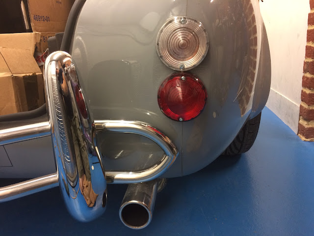
And bringing up the rear...


With a partially completed one to show the back of the light and how it needs to fit into body.


Now all the lights are on its time to start sorting out the rest of the wiring loom to get them lit!

Wednesday, September 16, 2015

Fly deflection device (also known as a windscreen)

Well, that took some time - the making and release of my windscreen for collection. Mainly down to the company doing the plating I'm told.

The fitting of this is pretty straightforward, the screen comes in 3 main parts. The screen in its frame plus the two uprights which slot through the precut body slots.

They key installation tool is the magic piece of timber to hold the screen at the correct angle - from memory I think it's 34" from top back edge of screen in the middle to the front edge of the rear cockpit return (lined up with the middle of the transmission tunnel)


Best to have it cut ready to receive the screen.
Then for my first fitting I attached both legs to the screen and then slotted it into the cut holes, applied the wooden gap tool for correct take and then tightened the legs against the scuttle hoop with a couple of clamps.


Now, as usual with these things there's a bit of jiggling and adjusting to get everything lined up.

Firstly a bit of washing up liquid and water applied under the screen rubber flap between rubber and body allows the screen to sit lower - from memory I think the suggestion was to allow 5 or 6 mm which leaves space for escutcheons plus a little wiggle room- check with AK if you're a fellow builder following my blog though.

Next I found the drivers side leg to be under a bit of strain from the body down to various alignment parameters.

Looking under the dash the leg wasn't anywhere close to the scuttle hoop.


So more jiggling and checking mid point alignment of screen vs dash and tunnel plus opening out the slot by a few mm improved this to a point where I was happy with it.

Then it's clamp and drill holes as per AK instructions - the further apart the upper and lower holes on the legs the more stable the screen will be.

I used 10mm 8.8 bolts but 8mm would be fine too.


And fitted. Just the escutcheons left to do. Makes a real difference to the appearance, looking like a car now!

Saturday, May 9, 2015

Shiny Stuff pt 2

I had no idea it's been such a long time since the last update. Progress is slow at the moment, partly shoulder related but also some of the tasks are requiring a bit of time to ensure I'm not making any mistakes. I have however ordered the windscreen which is due in a couple of weeks - feels like a significant step forwards.

So after putting it off for a while I needed to tackle the front nudge bar and overrider setup. Some just fit overriders, some quick lift jack points (race style but just cosmetic) or full nudge bar with overriders. Originally I was going to do nudge bar only until Mrs B pointed out it would be better to do all for the sake of paint work and other drivers in car parks.

It's a tricky one as where the fixing rods go through the body is all curves with little in the way of reference points to work from.
AK do mark a position for the holes but at this point I have no idea if they are where I need them to be - reason being is that there is a school of thought that says it's better to bend the studding rod to allow it to be horizontal as it passes through the body instead of an angle. This will make sense a bit later. Maybe. 

First things first, the overriders need attaching to the nudge bar. Again it's all curves and no guide markings either.

Rule number 1 is to ensure the top of the overriders line up with the top of the nudge bar. 


This is done by using a long straight edge and then some accurate measurements to find where to drill holes for bolts from inside of overriders. Repeat for the other side and then drill out.


Bolted up test for symmetry. 

Looking ok so far.

I inserted bolts into the stud fix position and using a camera tripod with a couple of modifications, made a jig for accurately  testing the position for fitting.


Those photos above don't show the bolts as my method of checking the holes marked on the body for drilling. However the hole positions are good so it's just a case of drill and then open out slowly with dremel and files and then mark up and fit brackets.

If I'd wanted to make things more complicated I could have tried to bend the studding as it comes out of the overrider so that the studding and tube assembly is parallel with the ground but doing this proved to be too difficult plus it's not obvious whether the body angle front to back would change with further suspension adjustment making it impossible at this stage to judge. 


Brackets attached to inner wing face - there's a degree of adjustment possible to get best alignment.


And there you have it. I know the transmission cooler looks wonky... When I fitted it there was no body to reference the radiator position. Hand welded radiator frame to blame. Not my welding I should add.

Holes just need opening out for grommets for nudge bar now.


Sunday, March 29, 2015

Shiny stuff Pt 1

One of the main things to do before painting is to fit all the shiny hardware... And then take it all off again!

Frustrating but the alternative would be to paint and then risk messing it up either by drilling in the wrong place or worse.

This includes lights, bonnet locks etc. Given I haven't bought these yet I've started on the fuel filler and rear nudge bar and overriders.


The rebated filler position on the AK is created deliberately to allow the Aston type filler cap to fit and still pass the IVA.
Whilst it's not strictly round hence the trianglular 'centre point' this is good enough to cut the hole for the underside of the filler flange to sit in the right place.

See below, now just need to decide how to fix it down. Bolts and nuts, self rappers or adhesive.

I need to acquire the right hose and then cut through the inner wing to feed into boot for tank connection.


The nudge bar overriders set up holes are marked on the body.

Using a level and comparing to boot floor mountin positions over the read rail I can see these are in an accurate position so just drill carefully and open out.


Photo below before I'd added the studding for lower position in overriders.


Will get another photo of fully positioned soon.

Just need to source some grommets to help protect paintwork and keep the elements out too.

Saturday, March 28, 2015

Final hot stuff post?


Hurray! My shoulder is getting better. It's not perfect yet but I'm able to start some less demanding tasks.

So on to finishing off the hot air management part of the heater.

The AK bodyshell comes with a fibreglass  plenum for the heater matrix.

This requires drilling and pipe fitting to feed ductwork which will lead hot air to the screen demist vents.
I'm choosing to also to provide heat for both the driver and passenger footwells too as the polo heater has plenty of grunt.


So using standard waste outlet pipe I've marked up the top of the plenum for drilling.

And a trial hole and test proves the interference fit I was lookin for - a small rap with a rubber mallet and this is held strongly.

With combined silicone adhesive sealant compound this should hold firm and be air tight too.


So with 4 holes drilled time for a quick check and mark up for where the adhesive will go to seal.


It's been a while since my trainers have made an appearance in the photos so thought I'd include the one above.
4 pipe outlets temporarily fitted.


Dr Who monster creators will be calling me up to help them with their next creation after they've seen the below.


I've decided to seal the hoses onto the outlets first before sealing it onto the body tub as the hose is a tight fit and it's easier to do now. The hose clips will eventually be removed.


Final preparation of the heater matrix above with making a foam insert and gluing that in position too. 

Note the holes either side of the matrix. I've made small brackets which will hold the plenum in place whilst sealing on.


Thankfully this will be hidden from view so the sealing has been thorough.


The last piece of this puzzle was to join the heater motor wires to longer pieces and feed through back into the cabin where they can be connected to an appropriate switch and fuse config.


Where cables come through the body they must be protected. Being a fan of doing the job properly (because chafing wires eventually make fires - you heard it here first!) I've chose to grommet the hole and feed conduit through too. The fan wires are inside the convoluted tube. 

(The other grommet hole is for the reverse light and neutral/park safety switch wires which come from the gear selector - ran them under the tub as I didn't want to have them running on top of the transmission tunnel as can be seen below)


I fired the engine up once this this was all set. The good news is hot air is plentiful.

The bad news is that the fan motor is squealing on medium and high speed. Which is a bit of a pain as it was fine when I tested it out of the car.

On to the desnagging list it goes :-(

Wednesday, February 4, 2015

Handbrake Pt1

As with many things in life chores get in the way of having fun, and with the usual work bunfight in Barcelona, rehearsing for a gig and breaking my big toe (in two places) I haven't had much time in January.

And now February. I have just had to have a shoulder operation, which means being in a sling for 4 weeks. Then another probable month before I can do any serious work on the car so I'm catching up with blog posts instead.

So having messed up the thread on one of the body attachment points from over zealous application of the handbrake when first testing it, I drilled out the thread, drilled right through the chassis to underside and aquired a longer bolt and nut to go through - so this is akin to the scuttle hoop attachments bolts now instead. Better in my view.

However the challenge still remains of the handbrake lever position.  With the hole now drilled through the body for the cable to pass through, the natural position for the handbrake to take is shown below

This is too far forwards and the top edge of the bracket is too high against the door sill lip. Next photo shows that more.


And the bottom inboard edge of the bracket will possibly interfere with seat at this point too. I removed and tidied 5mm from inboard edge of the bracket to help with that.

Looking at the image below one of the problems is clear - where the bracket has been welded the heat has caused it to move out of true 90 degree angle - probably removed from the jig a bit quickly. 


Having a brief chat with Jon at AK options were he'd replace it or I could give it a tonk with something heavy to bend the angle in first.

I took the latter and with a couple of large hits got it back to 90 degrees.

The XJS mounting bolts also need trimming down as they will interfere with internal trim panel.

With these things done the position is much better so I painted up with por15 rust prevention paint as the hand rack mechanism has a plastic cover over which I will put a leather cover too,

Finally mounting photo to follow... Which I've now taken and put below.


And no the blocks of wood aren't staying... It's not a Morgan you know!