Tuesday, October 28, 2014

Finally plucked up the courage

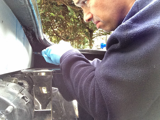
Yes, it can only mean one thing... Cutting another largish hole in the body, this time in a rather visible and significant location.

Transmission tunnel to be precise, for the gear shifter lever thing. 

It's not made easy that you cannot exactly rely on the transmission tunnel frame on the chassis as this is designed to not touch the actual fibreglass so instead a series of reference points from the body to chassis bolt holes are used instead. Coupled to this that its a 3d structure and not a flat plain makes it much more difficult. So I set about working out how I could transpose the location fixed to the chassis tunnel frame to the top of the fibreglass body 50ft away outside.

Having considered creating some sort of 3d mesh set of dimensions I came to my senses, set up a plumb bob line and combined that with tape measure and protector and the right position was marked up. 


Adding in additional tolerances all round for fitting this should be ok.


Marking the centreline of the tunnel is a complete red herring as I have no idea if the frame on the chassis sits perfectly symmetrically beneath it or not. And I'm not about to waste time measuring for curiosity's sake either.
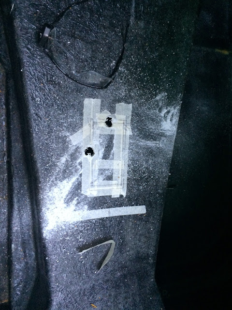

Next a couple of round holes for cable conduit and end of the lever pivot bolt clearance and it's ready for cutting out.


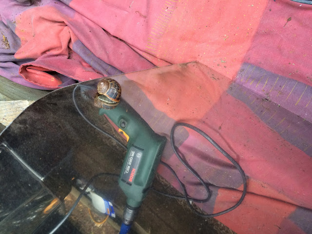
Add one masked loony with a fast spinning abrasive tool...


And we get the obligatory photoshop of one of my trainers. I might have to go back and count how many times they've got in on the act. 
More importantly one hole is cut. That's the last of the big prefit body jobs. One more small hole to open up in the engine bay and that will be ready.

Unlike the wire loom knitting that I'm still to finish sorting.

Saturday, October 25, 2014

More tidying trans cooler hoses

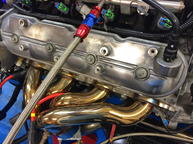
This current task seems to be without end and taking forever. One of the things I've been wondering is how to keep the two transmission cooler lines (braided hose in above photo) away from the exhaust below it. 


Eventually I hit upon making a bracket that could reach forwards and down from a nice lug on the transmission casing which would also double as a fixing position for some cables too. The lughole (clever eh?) can be seen below amongst the spaghetti.


Enter the worlds most oddest and complicated bracket yet...


The welding isn't too bad - my kind neighbour lent me his kit again.


One makeshift spray booth against the garage door.

I know I know, I must be becoming a little unhinged to need to dedicate so much time to one bracket (it's acid etched, primed and top coated - 2 coats of each)


And installed below.


Above the cunning cable conduit is held in position...


And the finished article installed and torqued up.

Next is finishing off the spaghetti tidying.

Sunday, October 12, 2014

A confession.

Ok... Have a look at the photo below and guess what's wrong with the picture.

If it's not obvious then have a look at the next one.


Or the next one


At this point you might have made out the letters D followed by R on a round shiny tube located between the engine mount and rubber bobbins.
Let me spell the rest of the word. 

"Draper 17 mm"

Yes. Somehow I have managed to leave a 17mm socket on the end of one of the engine mount bolts from when I torqued them up. What a total muff up! How did that happen? I remember at the time wondering where it had got to and ultimately thinking I'd thrown it out by accident so I bought another one.

It wouldn't poke out although it's loose meaning that nothing has been damaged as the engine isn't resting on it thank goodness.

So after feeling like a complete muppet for a couple of days I figured out a way of easily getting it out.

Loosen off the offside upper mount bolts on the bobbins but leave them on, trolley jack under the offside part of the sump and raised it up 5mm. This was enough to poke the socket out with the end of a long crowbar.


There you have the culprit above. All out, no drama. Thankful no engine lift out required.

Cladding is done!

Hurrah. I'm loathe to say it but I'm very glad this stage is over. Why I failed to make sure this was a factory fit option instead of me doing it I don't know but I've learnt a lot in the process of doing it myself.
So having repaired the bad bit of glass fibre, filled and coated with the rubber paint time for a bit of drilling and riveting (below) to fit the last cladding panel which sits on the front of the scuttle - above the bell housing.

I've put a sealant adhesive behind this panel and riveted at the top plus two low down at the sides.


The final parts to put on are the angle and top above drivers feet again sealed down with adhesive and then the angle corner drilled and riveted.


And then the two fillets which are not standard ak parts but I asked Jon to make to cover a couple of small gaps. I didn't drill out the other rivets choosing to fit over them. Possibly a mistake but there will be so much engine and exhaust headers in the way I don't think visually it matter. 

Just one last hole to open up for the bonnet hinge plus cutouts for gear lever and fuel filler and it's ready to put on the chassis! 

Saturday, October 11, 2014

Progress or anti progress?

Not sure that's a real term but for the life of me at the moment I cannot think any better.
The cladding in the engine bay has been difficult. However Jon at AK kindly sent me some better drill bits that really helped overcome the work hardening issue I was making for myself.

And with one side done I have a comedy fairground 'hall of mirrors'. 

More annoying is I turn round for 5 minutes and this happened. The cheek of it...it's not on my drill but is on the back of the offside panel I was about to fit


Having learnt from the nearside that I wasn't brutal enough on the bending into shape I took a firmer stance and got the offside a much better fit before starting on the drilling and rivets.


As a result this side took 35 minutes instead of 5 hours.


I drilled double holes and fed cable ties through the wings before fitting the cladding so that the wire looms to front lights can easily be attached.


You can just see one at the top of the wheel arch above. Now just to file off the ends of the rivets.

But this looks like progress I hear you say. We'll eventually yes however I've measured between the footwells in the engine bay and discovered that the body will not fit on over the exhaust headers whilst they are on the engine.
Given I've sealed them on this is a pain as I need to take them off, file off the hardened sealant and then redo once the body is on.


Wednesday, September 24, 2014

Small advances and coil pack relocation

Hmm. I think the 80/20 rule needs changing. The last 20% of jobs to do before getting the body on are taking forever. Luckily with no hard deadlines set  I can persuade myself not to rush... Instead I'm making more work for myself. 

Not happy with the length of brake pipe up to the master cylinder I've added a couple of lengthening pieces with joints.
Not necessarily obvious from the photo above but the master cylinder position is 11 inches above the chassis member, so I've allowed for that plus some slack to enable a neat run inside bonnet. Plus I've put last pipe retaining clips onto the chassis too.

Next I wasn't happy with the threads I've tapped for the fuel tank so I'm changing them from M8 to M10 to beef up the fixings and then I'm thinking of making a couple of additional straps as an added safety feature. This might be a bit overkill given I've done all the bolts as M10s now.

I had originally planned to move the coil packs, which hideously clutter the valve covers, after the body goes on however access is easier now so I've made a start. The below top right shows the kind of thing I'm talking about. In the car this engine was intended for these would be covered over by more plastic / sound proofing.


Another view of coil packs above. The metal bracket they are attached to weighs alot too.

So using a combination of the bracket shown below plus some soldering skills it should be easy to lengthen the signal cables allowing all to be tidied.


Below - one down, 6 more to go (for this bank)


Above, lengthened signal wires done and all joints tested with meter to make sure all the conductivity is good. Keeping the cable tidy and protected with convoluted tube is essential.

I took the opportunity to change the front O2 sensor routing at the same time so you can see above more of that leg of the loom is exposed.


Above and below - nearly finished. I can then use the old bolt holes to fix spark lead spacers to have the spark plug leads neatly led across the valve cover in parallel... Or maybe get some new shiny valve covers??


Wednesday, September 17, 2014

Gear selector pt2

Once I was happy with the position the lateral support bars were welded to the tunnel frame and then painted with more of the POR15 paint system.
Ready to weld

Masked invader


Not the prettiest welding but it will do.


Painted and ready for final fitting


I decided to drill and tap to make it easier for fastening and less faffing if I have to adjust once the body is on from underneath.


There are nylocks on the underside of the bolts just as a locking nut but shouldn't really need it. 
Just need to sort out some convoluted tube and cable joints and then this is finished.


Sunday, September 7, 2014

More Hot Stuff

The final piece for the polo heater was to drill holes to mount the speed resistor and wiring block on, fit the block and then mount in the car.


The block mounted, and all speeds tested. Not sure if I'm going to use all of them as I don't really want knobs on the dashboard so need to think about how I switch between them.

Just the valve for the hot water to go back on.


And fitted...
Glued, bolted, screwed and sealed. I suspect it may never come out again so hopefully I've not muffed it up!


Inlet air hose connected, and valve back on. I have a controller for the valve but undecided how I will use it yet.


And view from underside showing the seal on engine bay side all good too.

This was a big job, now complete!