Wednesday, September 24, 2014

Small advances and coil pack relocation

Hmm. I think the 80/20 rule needs changing. The last 20% of jobs to do before getting the body on are taking forever. Luckily with no hard deadlines set  I can persuade myself not to rush... Instead I'm making more work for myself. 

Not happy with the length of brake pipe up to the master cylinder I've added a couple of lengthening pieces with joints.
Not necessarily obvious from the photo above but the master cylinder position is 11 inches above the chassis member, so I've allowed for that plus some slack to enable a neat run inside bonnet. Plus I've put last pipe retaining clips onto the chassis too.

Next I wasn't happy with the threads I've tapped for the fuel tank so I'm changing them from M8 to M10 to beef up the fixings and then I'm thinking of making a couple of additional straps as an added safety feature. This might be a bit overkill given I've done all the bolts as M10s now.

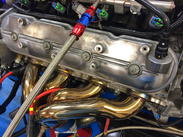
I had originally planned to move the coil packs, which hideously clutter the valve covers, after the body goes on however access is easier now so I've made a start. The below top right shows the kind of thing I'm talking about. In the car this engine was intended for these would be covered over by more plastic / sound proofing.


Another view of coil packs above. The metal bracket they are attached to weighs alot too.

So using a combination of the bracket shown below plus some soldering skills it should be easy to lengthen the signal cables allowing all to be tidied.


Below - one down, 6 more to go (for this bank)


Above, lengthened signal wires done and all joints tested with meter to make sure all the conductivity is good. Keeping the cable tidy and protected with convoluted tube is essential.

I took the opportunity to change the front O2 sensor routing at the same time so you can see above more of that leg of the loom is exposed.


Above and below - nearly finished. I can then use the old bolt holes to fix spark lead spacers to have the spark plug leads neatly led across the valve cover in parallel... Or maybe get some new shiny valve covers??


Wednesday, September 17, 2014

Gear selector pt2

Once I was happy with the position the lateral support bars were welded to the tunnel frame and then painted with more of the POR15 paint system.
Ready to weld

Masked invader


Not the prettiest welding but it will do.


Painted and ready for final fitting


I decided to drill and tap to make it easier for fastening and less faffing if I have to adjust once the body is on from underneath.


There are nylocks on the underside of the bolts just as a locking nut but shouldn't really need it. 
Just need to sort out some convoluted tube and cable joints and then this is finished.


Sunday, September 7, 2014

More Hot Stuff

The final piece for the polo heater was to drill holes to mount the speed resistor and wiring block on, fit the block and then mount in the car.


The block mounted, and all speeds tested. Not sure if I'm going to use all of them as I don't really want knobs on the dashboard so need to think about how I switch between them.

Just the valve for the hot water to go back on.


And fitted...
Glued, bolted, screwed and sealed. I suspect it may never come out again so hopefully I've not muffed it up!


Inlet air hose connected, and valve back on. I have a controller for the valve but undecided how I will use it yet.


And view from underside showing the seal on engine bay side all good too.

This was a big job, now complete!


Gear selector

The gear selector or shifter if you're American arrived a few weeks ago but it's taking a lot of fiddling to get things how I want them.
It's quite a simple and retro looking thing more in keeping with look of a Cobra whilst clearly not a replica item!

It comes with prettyuch everything needed to fit it to the car however due to the width of. The transmission and mine being a right hand drive, as it stands it's too far on the passenger side of the tunnel.

You can see the rod linkage on the rhs down the side of the transmission case. This has limited scope to allow the lever mechanism to be adjusted to drivers side.
Herb who runs Shiftworks is an incredibly helpful person and sent through a lever arm with 3/4" more offset to help at no charge from the US.


It's still not far enough so I am going to implement part 2 of the plan which is to introduce a dogleg pair of bends into the linkage rod to give the offset with appropriate clearance.

I've already done this once on the original  GM part so I know it works. Whilst the dogleg will stop the easy adjust reverse thread setup that the rod ends are set up with, I shouldn't have to adjust this once I have it setup right with the neutral safety and reverse light switching tested.  See below.


Now it's just height clearance to resolve. As I've decided not to mount on the fibreglass tunnel for strength and vibration reasons I need to fit a couple of steel supports to the tunnel cage to mount the shifter on.

These will be welded to the frame so that I don't have additional bolts to worry about in a tight space - thankfully a helpful neighbour has a portable arc welder so I will have to have a few practice goes to remind myself how to weld again and then commit!

I want to have the shifter as low as possible so that any protrusion of the shifter chassis is easily masked by a leather gaiter / shroud thing without it protruding upwards too much - hopefully the 1 1/2 inches at the moment should be ok. The overall position feels good when I sit in the chassis in seat position. The manual car builders don't have these issues - there's one position for the gear knob and that's it! I feel envious of this at the moment.


So this is the near final position, you can see linkage dogleg on LHS, the selector knob is central to the chassis. There is room to adjust if need be - all this is then translated into where I cut the slot in the transmission tunnel fibreglass to enable the body to go on. Technically I could have left this till afterwards but much easier to do now.

The final part of this puzzle is to manage the neutral safety and reverse light switch wiring. I am torn between having these running inside the body - easier to get to but a pain to cover over - or outside the reverse. If I sort now I can put in convoluted tube and lead back to engine bay relatively simply along side the transmission leg of the engine loom.


Above a rough sketch of how the neutral safety switch will be incorporated into the starter circuit providing illumination to Engine Start switch when only in neutral and park - and also only enabling the start switch for the same conditions. One thing I want to do is enhance that so once the engine is running the start switch is disabled too but that needs a bit more thinking about. Probably a line from the alternator charging / not charging indicator is a place to start.

Finally the immobiliser will need adding to this somehow but I'm not publishing how that's going to be done!